
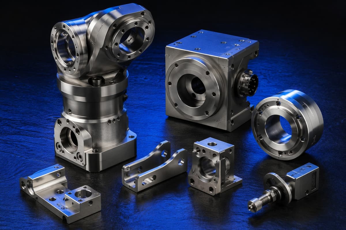
A drawing that says "±0.01 mm" on every dimension is a drawing that costs more than it needs to. Good tolerancing is the lowest-cost way to cut CNC cost without touching function.
A drawing that says "±0.01 mm" on every dimension is a drawing that costs more than it needs to. Good tolerancing is the lowest-cost way to cut CNC cost without touching function.
Quick answer
Specify a general tolerance for the whole drawing, such as ISO 2768-m for most features, and apply tighter tolerances only to the features that control fit, sealing or alignment. HC-Mold can machine to tolerances up to 0.005 mm, depending on the feature, material and part size, and surface finish down to Ra 0.4 µm. Every step tighter adds machine time, inspection and risk, so tolerance is a cost decision as much as an engineering one.
Key takeaways
- Use one general tolerance, then call out exceptions.
- Tolerance a feature because of its function, not out of habit.
- Material, size and temperature affect what is achievable.
- Say how a tolerance will be inspected, and whether it applies before or after finishing.
What a tolerance is
A tolerance is the allowed variation of a dimension. It protects fit and function, and it defines what the inspector accepts or rejects. Tolerances can be dimensional (a length or diameter), geometric (flatness, position, concentricity under GD&T) and finish-related (surface roughness).
General tolerances: ISO 2768
ISO 2768 sets default tolerances for dimensions without a specific tolerance. Typical linear values for the "fine" (f) and "medium" (m) classes are shown below. Check the standard itself for the full table.
| Nominal size | ISO 2768-f | ISO 2768-m |
|---|---|---|
| 0.5 to 3 mm | ±0.05 mm | ±0.1 mm |
| over 3 to 6 mm | ±0.05 mm | ±0.1 mm |
| over 6 to 30 mm | ±0.1 mm | ±0.2 mm |
| over 30 to 120 mm | ±0.15 mm | ±0.3 mm |
| over 120 to 400 mm | ±0.2 mm | ±0.5 mm |
Put the class in the title block, for example "General tolerances ISO 2768-m", and then call out only the exceptions.
Fits and limits: ISO 286
For shafts and bores that must fit together, use fit classes rather than free-hand plus and minus values. For example, an H7 hole has a lower deviation of zero and an upper deviation that grows with size.
| Hole size | H7 tolerance band (approx.) |
|---|---|
| over 6 to 10 mm | 0 to +0.015 mm |
| over 10 to 18 mm | 0 to +0.018 mm |
| over 18 to 30 mm | 0 to +0.021 mm |
| over 30 to 50 mm | 0 to +0.025 mm |
The mating shaft then gets a class such as g6 or h6, depending on the clearance you need. Confirm exact values in the standard.
How tolerance affects cost
As a general rule, cost rises steeply as tolerance tightens:
- Slower finishing cuts and more tool changes
- More careful fixturing and fewer parts per set-up
- More inspection time, often with a CMM, and temperature control for the tightest values
- Higher scrap risk
The cost curve is non-linear, so moving from ±0.1 to ±0.05 mm is a smaller step than moving from ±0.02 to ±0.005 mm. See the CNC cost guide for how tolerance sits with other cost drivers.
What affects achievable tolerance
| Factor | Why it matters |
|---|---|
| Material | Aluminum, stainless steel, titanium and PEEK behave differently when cut and when stress is released |
| Part size | Larger parts see more thermal movement |
| Wall thickness | Thin walls deflect under cutting forces |
| Features | Deep holes, long slender shafts and thin floors are harder to hold |
| Set-ups | Features machined in different set-ups depend on datum accuracy |
| Finishing | Anodizing or plating adds thickness, so say whether the dimension applies before or after finishing |
HC-Mold machines more than 50 materials on 3-, 4- and 5-axis equipment. A 5-axis machine can hold related features in one set-up. See 5-axis CNC for OEM programs.
How to specify tolerances well
- Set a general tolerance for the drawing.
- Identify functional features: mating faces, bores, sealing surfaces and datums.
- Use GD&T (position, flatness, concentricity) where it describes function better than plus and minus.
- Define datums that match how the part is used and inspected.
- State the surface finish only where it matters.
- Say how it is measured if the method matters, for example CMM report on named features.
- Mark before-or-after finishing for coated surfaces.
Common tolerance mistakes
- Blanket tight tolerances on every dimension
- Tolerances that are tighter than the material, size or process can reasonably hold
- Missing datums, so the inspector must guess
- Copying tolerances from an injection-molded or cast part design
- Forgetting coating thickness
- Asking for a surface finish finer than the function needs
Worked example (illustrative, not a customer project)
An aluminum bearing housing needs a bore that accepts a 20 mm bearing, four mounting holes and a flat sealing face. A sensible drawing would include:
- General tolerance ISO 2768-m in the title block
- Bore Ø20 H7 (about 0 to +0.021 mm), with a surface finish callout where the bearing sits
- A position tolerance on the four mounting holes relative to the bore axis, instead of plus and minus on each hole
- Flatness on the sealing face, with a roughness value only on that face
- Everything else left to the general tolerance
The result is one tight fit, one geometric control and one finish requirement instead of dozens of tight dimensions. Cost drops and inspection gets easier.
Inspection and reports
Tell the supplier which features need a measurement report, how many pieces to measure (all, a sample or first article only) and which method applies. A CMM report on named features, a first-article report and a material certificate are common requests. HC-Mold's CNC prototypes come with an inspection report. Asking for reports on every dimension raises cost, so limit them to critical features.
What to include in your RFQ
2D drawing with the general tolerance class and critical dimensions, STEP model, material, quantity, finish and inspection or report requirements. Use the CNC RFQ checklist. HC-Mold's inspection approach is on the inspection page. CNC lead time is 5 to 10 days and prototypes take 3 to 5 days, depending on the part.
FAQ
How tight can HC-Mold hold CNC tolerances?
Up to 0.005 mm, depending on the feature, material and part size.
What is a good general tolerance for CNC parts?
ISO 2768-m suits most non-critical features. Use ISO 2768-f or tighter values only where function requires it.
Does tighter tolerance always cost more?
Yes. It needs slower cuts, more careful fixturing and more inspection, and the cost rises steeply at the tightest values.
Do tolerances apply before or after anodizing?
State it on the drawing. Coatings add thickness, so the answer changes the machined size.
What surface roughness can you achieve?
Down to Ra 0.4 µm, depending on the feature and material. Specify it only on surfaces where it matters.
Check your tolerances before you order
Upload your drawing with critical dimensions. Engineers review which tolerances are needed and which can be relaxed. We reply within 12 hours.
Talk to HC-Mold engineering
Free DFM · reply ≤12h · quote ≤24h on complete RFQ · ISO 9001:2015 · Dongguan, China