
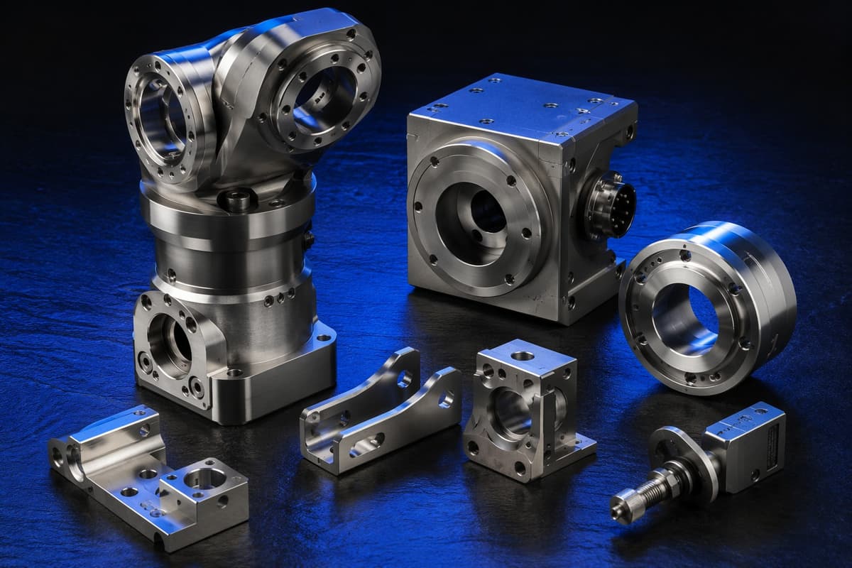
Die casting makes complex parts fast, but its defects differ from injection molding and CNC. Many appear only after machining, so it pays to know them before the first sample.
Die casting makes complex parts fast, but its defects differ from injection molding and CNC. Many appear only after machining, so it pays to know them before the first sample.
Quick answer
The most common aluminum die casting defects are porosity (gas or shrinkage), cold shuts and misruns, flash, soldering or die sticking, blisters, cracks and flow marks. Most come from five areas: part design (uneven walls, sharp corners), gating and venting, die temperature and lubrication, injection speed and pressure, and metal quality. Fixes belong in design first, then die modification, then process settings. The table is general guidance. Real causes depend on the alloy, die and machine.
Key takeaways
- Porosity is the defect most likely to affect sealing and machining.
- Uniform walls, draft, radii and good gating prevent most defects.
- Agree acceptance criteria and test methods before production.
- Plan machining stock and test sealing faces after machining.
Defect guide
| Defect | What you see | Common causes | Typical fixes |
|---|---|---|---|
| Gas porosity | Round pores, often near the surface or in thick sections | Trapped air, poor venting, lubricant gas, high speed | Improve venting and overflows, review gating, adjust speed, consider vacuum assistance |
| Shrinkage porosity | Irregular voids in thick sections | Insufficient feeding, thick hot spots | Even out thickness, adjust gate and intensification, improve die cooling |
| Cold shut | Visible line where metal fronts did not fuse | Low metal or die temperature, long flow path | Raise temperatures, shorten flow, change gate location |
| Misrun, short fill | Incomplete cavity filling | Low temperature, slow fill, blocked vents | Raise temperature, increase speed, clear vents, enlarge gates |
| Flash | Thin metal at parting lines | Worn die, low clamp force, high pressure | Repair or re-fit the die, adjust clamp and pressure |
| Soldering or sticking | Metal sticks to the die and tears | Hot die spots, lubricant issues, low draft | Add draft, improve cooling and spray, adjust alloy and die coating |
| Blisters | Raised bubbles after heat treatment or coating | Subsurface porosity expanding | Reduce porosity, avoid heat treating cast parts unless the process allows it |
| Cracks | Fine lines at stress points | Thermal stress, sharp corners, uneven cooling | Add radii, balance cooling, adjust ejection |
| Flow marks, lines | Surface patterns following the flow | Low die temperature, slow filling | Raise die temperature, adjust speed and gating |
| Distortion | Part warps or twists after ejection | Uneven cooling, ejection force | Balance cooling, adjust ejection and trimming |
Design rules that prevent defects
- Keep wall thickness as uniform as function allows, and transition gradually.
- Add draft and generous fillets to help fill and ejection.
- Avoid heavy sections, which cause shrinkage porosity.
- Plan ribs and bosses with the same care as in plastic parts.
- Agree early which faces will be machined, with enough machining stock, because machining can expose subsurface pores. See the aluminum die casting guide.
Gating, venting and cooling
The path metal takes through the die decides much of the quality. Gate position and size control how the cavity fills. Vents and overflow wells carry air and cold metal out of critical areas. Cooling channels near thick sections help feeding and reduce shrinkage porosity. These are die-design decisions, so review them in the DFM stage, before the die is built. Tooling is a major investment: see how mold cost is built up.
Testing and acceptance
| Method | Use |
|---|---|
| Visual inspection | Surface defects, flash, flow marks |
| Dimensional inspection | Fit and flatness after trimming and machining |
| Leak or pressure test | Sealed housings and covers |
| Density or sectioning checks | Porosity assessment on sample parts |
| X-ray inspection | Internal defects where required (ask the supplier whether this is available) |
Agree before production what porosity level is acceptable, in which areas, and how it is checked. Sealing faces are usually the strictest. HC-Mold uses SPC monitoring and full batch inspection in production, described on the inspection page.
Machining and impregnation
Machining can reveal pores just under the surface. If a sealing land fails, agree in advance whether you will impregnate or scrap, so the decision is not improvised. Test leaks after machining and before final assembly. For precision features, see tolerances explained.
Volume and minimums
Die casting suits higher volume because the die is a large upfront cost. HC-Mold's die casting MOQ is 1,000 pcs. For fewer parts, CNC may be the better route: see CNC vs injection molding for low volume and the die casting page.
What to send for a defect review
Photos, the STEP file, the alloy, which faces are machined, sealing or pressure requirements, defect location and the volume produced. We reply within 12 hours.
FAQ
What causes porosity in die casting?
Trapped air, poor venting, lubricant gas and shrinkage in thick sections. Fixes include better venting and gating, even wall thickness and better die cooling.
Can porosity be eliminated completely?
Rarely. The aim is to control where it occurs and how much is acceptable, especially on sealing and machined faces.
What is a cold shut?
A visible line where two metal fronts met but did not fuse, usually caused by low temperature or a long flow path.
How do I test a die-cast housing for leaks?
Use a leak or pressure test after machining, with limits agreed before production.
What is the die casting MOQ at HC-Mold?
Die casting starts from 1,000 pcs.
Have a die casting quality problem?
Send a photo, your STEP file and the alloy. Engineers review whether the cause is design, tooling or process. We reply within 12 hours.
Talk to HC-Mold engineering
Free DFM · reply ≤12h · quote ≤24h on complete RFQ · ISO 9001:2015 · Dongguan, China