
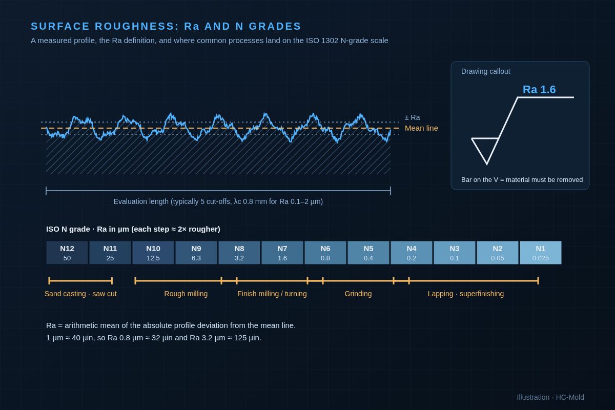
A surface roughness chart maps Ra values to ISO N grades and to the processes that produce them. Ra 3.2 µm (125 µin, N8) is the usual as-machined CNC finish, Ra 1.6 µm (63 µin, N7) is a fine machined finish, Ra 0.8 µm (32 µin, N6) is the limit of good milling and turning, and Ra 0.4 µm (16 µin, N5) or smoother normally needs grinding, lapping or polishing.
Ra is the number most drawings use to call out surface finish, and it is also the number most often over-specified. This page gives the full Ra chart in micrometers and microinches, the range each process can reach, how to write the callout on a drawing, and how to choose the roughest finish that still does the job, which is where the cost savings are.
What surface roughness and Ra mean
Surface roughness is the fine, closely spaced irregularity left on a surface by the process that made it: tool marks from a cutter, grit scratches from grinding, the grain of a sand mold. It is one part of surface texture. The other two are waviness (longer-wavelength undulation from vibration or deflection) and lay (the direction of the dominant pattern).
Ra (arithmetic average roughness, also written AA or CLA on older drawings) is the average absolute height of the profile above and below its mean line over the evaluation length. A profilometer stylus traces the surface, filters out waviness with a cut-off length (λc), and averages the result. For most machined surfaces between Ra 0.1 and 2 µm the cut-off is 0.8 mm and the evaluation length is five cut-offs, 4 mm.
Because Ra is an average, a surface with one deep scratch and a surface with even fine marks can show the same Ra. That is why sealing and bearing surfaces sometimes add Rz (average peak-to-valley height) to the callout.
Surface roughness chart: Ra, microinches and N grades
The N grades come from ISO 1302. Each step roughly doubles Ra. Microinch values are rounded by convention (1 µm ≈ 39.4 µin).
| N grade | Ra (µm) | Ra (µin) | What the surface looks like | Typical use |
|---|---|---|---|---|
| N12 | 50 | 2000 | Coarse, deep marks | Flame-cut or sand-cast surfaces left as is |
| N11 | 25 | 1000 | Heavy saw or rough-cut marks | Clearance surfaces on castings and weldments |
| N10 | 12.5 | 500 | Clearly visible, felt with a fingernail | Rough machining, non-functional faces |
| N9 | 6.3 | 250 | Visible tool marks | Non-mating machined faces, structural parts |
| N8 | 3.2 | 125 | Tool marks visible but smooth to touch | Standard as-machined CNC finish |
| N7 | 1.6 | 63 | Faint tool marks | Mating faces, press fits, parts to be anodized for looks |
| N6 | 0.8 | 32 | Marks barely visible | Static seal faces, bearing seats, sliding parts |
| N5 | 0.4 | 16 | Semi-bright, no visible marks | Dynamic seals, shafts in bushings, high-fatigue areas |
| N4 | 0.2 | 8 | Bright | Precision bearing journals, hydraulic spools |
| N3 | 0.1 | 4 | Near mirror | Gauges, precision sealing faces |
| N2 | 0.05 | 2 | Mirror | Optical mold inserts, lapped faces |
| N1 | 0.025 | 1 | Mirror, no visible texture | Gauge blocks, optical components |
Ra by manufacturing process
Each process has a range it can hold reliably in production and a finer value it can reach with extra care, slower feeds or a final pass. The table below shows typical industry ranges. The result on a real part also depends on the material, tool condition and machine rigidity.
| Process | Typical Ra (µm) | Finer with extra care (µm) |
|---|---|---|
| Sand casting | 12.5–25 | 6.3 |
| Die casting | 1.6–3.2 | 0.8 |
| Rough milling | 6.3–12.5 | 3.2 |
| Finish milling (3/4/5-axis) | 1.6–3.2 | 0.8 |
| CNC turning | 0.8–3.2 | 0.4 |
| Drilling | 3.2–6.3 | 1.6 (reamed: 0.8–1.6) |
| Wire EDM | 1.6–3.2 | 0.4 with skim passes |
| Surface or cylindrical grinding | 0.4–1.6 | 0.1 |
| Honing | 0.1–0.4 | 0.05 |
| Lapping, superfinishing | 0.05–0.2 | 0.025 |
| Hand polishing | 0.1–0.4 | 0.025 (mirror) |
Soft aluminum alloys and free-cutting brass finish more easily than stainless steel or titanium at the same settings. Plastics such as POM machine smoothly; nylon and PEEK tend to leave fuzz on edges. For tighter numbers on a specific part, ask for a DFM review rather than relying on a chart.
Ra vs Rz vs Rq (RMS): can you convert them?
| Parameter | What it measures | Relation to Ra |
|---|---|---|
| Ra | Average absolute deviation from the mean line | Reference |
| Rq (RMS) | Root-mean-square deviation | About 1.1 × Ra on turned or milled surfaces; higher on random textures |
| Rz | Average of peak-to-valley heights over five sampling lengths | Often 4–8 × Ra on machined surfaces, but no fixed ratio |
| Rt / Rmax | Largest single peak-to-valley height | Catches isolated scratches Ra hides |
Rq and Ra are close enough that an old "63 RMS" drawing can be treated as roughly Ra 1.6 µm. Rz is different: it depends on the shape of the profile, so the ratio changes from one process to another. If a European drawing says Rz 6.3, do not convert it to Ra and quote against that. Measure Rz, or ask the designer which parameter matters.
How to read and write a surface finish callout
Surface texture symbols are defined in ISO 21920-1 (which replaced ISO 1302 in 2021) and, on US drawings, ASME Y14.36. The basic symbol is a check mark with the requirement written over the long leg.
- Plain check mark: any process is allowed.
- Check mark with a bar closing the V: material must be removed (machining, grinding).
- Check mark with a circle in the V: material removal is not allowed; the surface stays as cast, molded or forged.
Write the parameter and the value, for example Ra 1.6 on an ISO drawing or 63 (µin) on an ASME drawing. You can add an upper and lower limit (Ra 0.8 max, Ra 0.2 min, which matters for O-ring grooves that must hold lubricant), the process ("ground"), and the lay direction:
| Lay symbol | Meaning |
|---|---|
| = | Lay parallel to the view where the symbol is drawn |
| ⊥ | Lay perpendicular to that view |
| X | Crossed in two directions |
| M | Multidirectional |
| C | Circular, about the center |
| R | Radial |
| P | Particulate, non-directional (blasted, EDM) |
Put a general note in the title block ("All machined surfaces Ra 3.2 unless otherwise specified") and add individual symbols only on the faces that need something finer. One symbol per critical face is easier to quote and inspect than a symbol on every face.
Which Ra to specify: a decision table
The rule engineers repeat is the right one: specify the roughest finish that works. The values below are typical starting points used across industry; seal and bearing suppliers publish their own limits, and theirs win.
| Surface function | Typical Ra (µm) | Comment |
|---|---|---|
| Non-mating faces, internal pockets | 3.2–6.3 | Leave as machined |
| Bolted or mating flat faces | 1.6–3.2 | Ra 3.2 is enough for most |
| Cosmetic faces to be anodized | 1.6, then bead blast | Anodizing shows tool marks; blasting hides them |
| Static O-ring or gasket faces | 0.8–1.6 | Finer (≤0.8) for gas sealing |
| Press-fit bores and bearing seats | 0.8–1.6 | Pair with an ISO 286 fit |
| Dynamic seals, shafts in bushings | 0.2–0.4 | Usually ground or polished |
| Optical or mirror surfaces | ≤0.05 | Lapped or diamond polished |
For most housings and brackets, Ra 3.2 on everything and Ra 1.6 or 0.8 on two or three functional faces is the right call. A blanket "Ra 0.8 all over" usually means slower feeds on every face, longer cycle time and more inspection, with no gain in function.
How surface finish affects cost and lead time
Cost does not rise smoothly with smoother Ra. It rises in steps, each time the finish needs a different operation:
- Ra 3.2: standard finishing pass, no extra cost.
- Ra 1.6: slower feed or a dedicated finishing tool on the affected faces. Small increase in cycle time.
- Ra 0.8: careful milling or turning with sharp tools; on hard or gummy materials it may need grinding.
- Ra 0.4 and below: a separate grinding, honing, lapping or polishing operation, a second setup, and roughness inspection on each part. This is where lead time grows.
Each extra step also adds a measurement. A profilometer reading takes a minute, but on 500 parts with three callouts each it becomes real inspection time.
How finishing processes change Ra
- Bead blasting replaces directional tool marks with a uniform matte, non-directional texture (lay symbol P). It hides marks but does not make a surface smoother in Ra terms; fine media gives a lower Ra than coarse.
- Anodizing (Type II, MIL-A-8625) follows the machined surface closely, so visible tool marks stay visible. Hard anodizing (Type III) builds a thicker layer and usually raises Ra slightly.
- Plating and powder coating add thickness; powder coat fills fine marks but adds 50 µm or more, which affects fits.
- Polishing and electropolishing lower Ra but round sharp edges and can shift tight dimensions.
If a coated face has a functional Ra, state whether the value applies before or after coating. More detail on coatings: CNC aluminum machining and anodizing.
Molded parts: SPI finishes and their Ra
An injection molded part copies the finish of the mold steel, so plastic parts are specified by the mold finish, usually to the SPI (now PLASTICS Industry Association) scale. The Ra values below are the typical ranges published for each grade.
| SPI grade | Finishing method | Typical Ra (µm) | Use |
|---|---|---|---|
| A-1 / A-2 / A-3 | Diamond buff (#3, #6, #15) | 0.012–0.10 | Lenses, clear covers, high-gloss parts |
| B-1 / B-2 / B-3 | Grit paper (600, 400, 320) | 0.05–0.32 | Semi-gloss consumer parts |
| C-1 / C-2 / C-3 | Stone (600, 400, 320) | 0.35–0.70 | Matte parts, good release |
| D-1 / D-2 / D-3 | Dry blast (glass bead, oxide) | 0.8–18 | Textured, non-glare, hides sink and flow lines |
A-grade polish needs a polishable mold steel. NAK80 is our usual choice for high-gloss surfaces, and E420/S136 stainless is available when the resin or the environment calls for it. Texture and polish are set face by face in the mold quote; see parts of an injection mold and P20 vs H13 mold steel.
What to put on your drawing and RFQ
- A general Ra note for all machined surfaces (Ra 3.2 in most cases).
- Individual symbols with Ra (or Rz) on each functional face, plus lay direction if it matters.
- Whether the value applies before or after anodizing, plating or blasting.
- For molded parts, the SPI grade or texture reference for each visible face.
- Whether you need measured roughness values in the inspection report.
From HC-Mold's side: our CNC machining holds down to Ra 0.4 µm, and every order ships with a 3D measurement report. When we reviewed the 78 RFQs that came through our website, only 4 described a surface finish or texture requirement at all, and just one gave an Ra value (Ra 6.3 µm on all machined faces). Most buyers leave finish to the supplier, which is when cosmetic disputes start. A single general note and two or three face callouts prevent that. The free DFM review flags callouts that are tighter than the function needs. See also CNC machining tolerances and the CNC machining RFQ checklist.
FAQ
What does a 125 or 32 surface finish mean?
They are Ra values in microinches, common on US drawings. 125 µin is Ra 3.2 µm (N8), the standard as-machined finish. 32 µin is Ra 0.8 µm (N6), a fine finish for seal faces and bearing seats.
What Ra can CNC machining achieve?
Standard CNC milling and turning give Ra 1.6–3.2 µm. With sharp tools and a dedicated finishing pass, Ra 0.8 µm is practical, and fine turning can reach Ra 0.4 µm. Smoother values usually need grinding, honing or polishing.
Is Ra the same as RMS?
No. RMS (Rq) is the root-mean-square of the profile, typically about 1.1 times Ra on machined surfaces. For older drawings the two are often treated as equivalent, but on random textures the gap is larger.
Can I convert Ra to Rz?
Only roughly. On machined surfaces Rz is often 4 to 8 times Ra, but the ratio depends on the process and the profile shape. If a drawing specifies Rz, measure Rz rather than converting.
What is the smoothest finish for an injection molded part?
SPI A-1, a diamond-buffed mold finish with Ra of about 0.012–0.025 µm. It needs polishable steel such as NAK80 or S136 and is used for lenses and high-gloss covers.
Get your finish callouts checked
Send your drawing or STEP file with the finish notes. We return a free DFM review that flags over-specified Ra callouts and a quote within 24 hours on a complete package. See our CNC machining services.
Written by HC-Mold Engineering Team · Last updated: 2026-11-01
Talk to HC-Mold engineering
Free DFM · reply ≤12h · quote ≤24h on complete RFQ · ISO 9001:2015 · Dongguan, China